
Seven cases where you should buy from someone else: functional safety, guaranteed determinism, IEC 61131-3 specs,...
Latest posts
-
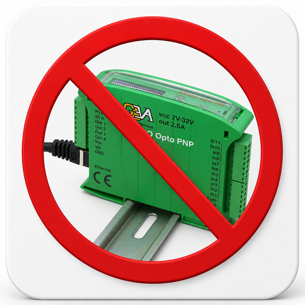 When NOT to use a GEVINORead more
 -
 Da Ladder e testo strutturato a GEVINO con l'aiuto dell'IA: costi ricorrenti a confronto, cosa si converte davvero, cosa non si converte, e la sequenza di migrazione a rischio più basso.Read more
The logic of a small machine fits on one printed page and has not changed in ten years. The bill of materials changes...
-
 Alarm Handling and I/O Monitoring: PLC Safety Logic Without Writing a Line of CodeRead more
"Artificial intelligence only writes toy examples": it is the most common objection, and it is fair. So we gave it...
-
 Industrial Retrofitting and Modbus RS485: Get Old Machines Onto the Network Without Losing Your MindRead more
There is a press from 1998 in the corner of the shop floor: it works perfectly and has no idea what Industry 4.0 is....
-
 From Idea to PLC Code in 2 Minutes: AI Writes a Conveyor Belt's Control LogicRead more
A photocell, a belt, a red lamp. Until recently, turning that description into a working program took a skilled...
-
 Arduino Is Not Industrial? Let's Clear Up the MisconceptionsRead more
Many engineers believe Arduino is suitable only for hobby projects. In reality, industrial reliability depends on...
-
 How to Program a PLC with Artificial Intelligence in 2026Read more
Discover how Artificial Intelligence is transforming PLC programming. Learn how ChatGPT, Claude Code, and...
-
 Why Choose GEVINO Instead of a Traditional PLC?Read more
GEVINO challenges traditional PLCs with lower costs, no software licenses, AI-assisted programming, and maximum...
Blog categories
Search in blog
Archived posts
Alarm Handling and I/O Monitoring: PLC Safety Logic Without Writing a Line of Code
"Artificial intelligence only writes toy examples"
It is the most common objection, and it is a fair one. Blink an LED, read a sensor, print a value: fine for a demonstration, useless inside an electrical cabinet.
So let us hand it the least toy-like task in automation: filtering inputs, recognising an abnormal condition that persists over time, and reporting it in a way somebody will take seriously. Then let us look at what comes out.
Why filters and delays exist
A digital input is not an ideal switch. It is a physical contact, at the end of a cable, inside a cabinet full of switching loads. Between the "zero" and the "one" there are always a few thousandths of a second of confusion:
- Mechanical bounce. A limit switch or a relay rebounds for 5–20 thousandths of a second before settling. A controller that looks at its inputs thousands of times a second, with no filter, counts one event as fifteen.
- Induced noise. A contactor opening a few centimetres away injects a spike into the signal cable running alongside it. The opto-coupler blocks the energy, but it does not invent a clean edge.
- Legitimate transient conditions. Two sensors overlapping for four hundredths of a second during a normal transfer are not a fault. The same two sensors overlapping for half a second are.
This is why every serious alarm has a time attached to it. "Input active" is not an alarm condition. "Input active, without interruption, for longer than the process could legitimately require" is.
Getting this wrong produces the most expensive failure in automation, and it is not an electrical one: it is an alarm the operators stop believing. First they ignore it, then they silence it out of habit, and eventually somebody bypasses it. The day it sounds for a real reason, nobody is looking at it any more.
How the artificial intelligence knows the machine's constraints
A model writing generic code picks more or less at random between the right and the wrong way of handling time. A model working on a GEVINO project does not, because the rule is written where it will certainly read it: in the technical document supplied with every board, on the first page.
The rule says, in essence: the program must never stop and wait. It has to supervise everything at once, all the time. That is the principle every PLC is built on, and it is exactly what separates an industrial program from a test-bench one.
The board also comes with a ready-made timer that behaves like the timers of traditional PLCs: while the condition is not met it stays at zero, and it only trips once the condition has held continuously for the time you set. The assistant uses it correctly because the example sits right there, next to the program.
It is worth saying plainly to anyone evaluating this way of working: the quality of the generated program depends far less on the AI model than on whether the board's manufacturer took the trouble to write its own rules in a format machines can read too.
The test: what we asked for
"Write the logic for GEVINO to supervise 4 opto-isolated digital inputs. If two inputs stay active at the same time for more than 500 milliseconds, trigger an alarm buzzer and send a notification with a snapshot of the input states."
What the delivered program does
- It filters the four inputs one by one. A signal is believed only after it has held steady for two hundredths of a second.
- It counts how many inputs are active at every moment, without ever stopping its watch on the others.
- It trips the alarm only after half a second of continuous overlap. If either signal drops in the meantime, the count starts again from scratch.
- It sounds the buzzer and lights the board's front indicator.
- It sends a single notification, at the moment the alarm trips — not a burst of repeated messages for as long as the condition lasts.
- It attaches the input snapshot to that notification: which ones were active, how many, and how long the machine had been running. The message arrives on a computer connected to the PLC and reads like this: "ALARM: overlap longer than 500 ms — active inputs: 1 and 3".
- It reports the recovery too, when the condition clears.
Why this is not a toy example
Four details separate this program from a demonstration. They are also the four things worth checking on any alarm logic, generated or hand-written.
- Every input has its own filter. A single shared filter would let a noisy channel mask the clean one next to it.
- Half a second continuous, not half a second since I first saw it. It sounds like the same thing and it is not: the second version trips on a series of very short overlaps — precisely the noise we set out to exclude.
- It does not sound at power-up. If the cabinet is energised with two sensors already made — a part left in the machine from the previous shift, say — the alarm does not fire instantly, but only after its regular half second. It is an easy mistake to make, and it always surfaces at the worst moment: the first restart after a stoppage.
- The snapshot is taken at the instant of the alarm, not afterwards. This is the classic diagnostic error: attaching the current input state to the message. By the time anyone reads that line, the sensors will have moved on long ago and the snapshot will tell them nothing.
The one decision left to the engineer
As written, the buzzer follows the condition: it stops when the overlap ends. In many plants you want the opposite — a latched alarm that stays on until an operator acknowledges it, so that a five-second fault at three in the morning is still visible the next day.
That is a three-line change, and above all it is a process decision, not a programming one. The artificial intelligence produced a defensible behaviour and made it explicit enough to argue with. Which is exactly what you ask of a colleague.
One boundary deserves to be stated clearly: this is process alarming, not functional safety. Emergency stops, light curtains and guard interlocks belong to a certified safety module, wired in hardware. No program — written by an artificial intelligence or by an engineer with twenty years' experience — replaces that component.
Why an open architecture beats a closed system
Compare what you can do with this logic on the two platforms.
On a closed system, the program lives inside a proprietary file, editable only with the manufacturer's software, on a workstation with an active licence. The diagnostics go wherever the manufacturer decided. Extending it to send alarms to the company system means buying a gateway module.
On GEVINO, the same logic is a text file. You can keep it in your own company archive, compare two versions to see what changed and who changed it, have it reviewed by a colleague or by an artificial intelligence, and add to it — with the same free tools — logging to a memory card, a web page reachable from the company network, a link to the line PLC, or a text message to the engineer on call. The alarm logic does not change: you only add to it.
Underneath, the hardware is the part that must leave no room for interpretation: dual-polarity opto-isolated inputs, short-circuit-protected outputs, protection against electrostatic and electromagnetic interference, DIN-rail enclosure, industrial screw terminals. The openness is in the software, where it saves money. The robustness is in the hardware, where it prevents warranty returns.
GEVINO PLCs are designed and manufactured in Italy by GEVA Elettronica.
Browse the models in our online shop, or write to email@gevaelettronica.it: describe the cabinet you need to build and we will tell you which configuration it takes.
Posted in:
GEVINI
Related posts
-
Why Choose GEVINO Instead of a Traditional PLC?
GEVINO challenges traditional PLCs with lower costs, no software licenses, AI-assisted programming, and maximum...Read more
-
How to Program a PLC with Artificial Intelligence in 2026
Discover how Artificial Intelligence is transforming PLC programming. Learn how ChatGPT, Claude Code, and...Read more
-
Arduino Is Not Industrial? Let's Clear Up the Misconceptions
Many engineers believe Arduino is suitable only for hobby projects. In reality, industrial reliability depends on...Read more
-
From Idea to PLC Code in 2 Minutes: AI Writes a Conveyor Belt's Control Logic
A photocell, a belt, a red lamp. Until recently, turning that description into a working program took a skilled...Read more
-
Industrial Retrofitting and Modbus RS485: Get Old Machines Onto the Network Without Losing Your Mind
There is a press from 1998 in the corner of the shop floor: it works perfectly and has no idea what Industry 4.0 is....Read more
Leave a comment